Description
This epic guide is made by Ritehunter. If you still can't understand logic gates even after reading this guide, try this web-app that simulates logic gates.
If you don't understand how does the logic gates works, this is the place you can find it. This guide also includes some useful combinations of Logic gates (like NAND, NOR etc...), so it is organized to two groups - Logic Gates and Logic Gates Combinations.
You can click on the gate's name to open up a page with detailed info about it. Every gate has its own slideshow showing its behavior.
Logic Gates
This is part of the Logic elements guide. To see Logic gates combinations and flip-flops guide, go at this page.
Think of gates as a some kind of gate which only allows certain things to be let in.
Gates can also be rotated by tapping on them and so their input and output areas change.
Logic AND Gate
- This is the gate that has the letter "A" on it
- This gate requires the two signals on its side to be on
- Once both signals are on, the gate will transmit a signal from its top
- However, if only one signal is on or no signal is on at all, the gate will be off


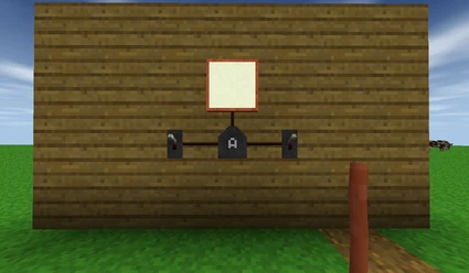
Just to recap - AND Gate gives off a signal only if the first input is on AND the second input is on (explains the name "AND")
Logic OR Gate
This is the gate with the "O" on it.
- It gives off a signal if either signal from its side is on
- Even if both signals are on, the OR Gate will still give off a signal
- However, if there is no signal at inputs, the gate does not give a signal


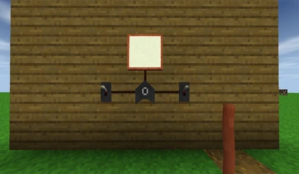
Just to recap -
OR gates give off a signal if at least one of the inputs are on.
OR Gate gives a signal if first OR second OR both inputs are recieving an electric current (explaining the name "OR")
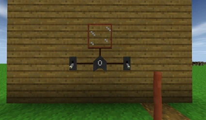
Logic XOR Gate
This is the gate with "X" on it
- XOR Gates will gives off a signal if only one signal is on
- Unlike Or Gates, XOR Gates will turn off when both signals are on


Just to recap -
- XOR Gate is almost like the Or Gate except that it turns off when both are on
- X means exclusive
- It will turn on when one input is on but not both
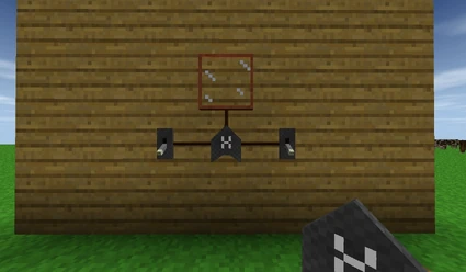
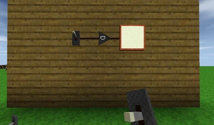
Logic NOT Gate
This is the gate with the "N" on it
- This gate only has one input and that is at the bottom
- This gate inverts the signal (if the signal is on, it turns it off)
- And vice versa, if the signal is off it turns it off
You can string them together and if you know math or grammar well enough, two negatives negate each other (when in a positive operation)
Think of the childish not not not not ... thing. An even amount of Nots make a positive while an odd makes things negative.
Like in this example - two NOT gates negate each other, so the final output will be the same as input.
OK, another recap -
- A NOT gate will turn the signal to the other state ( i.e. on to off, off to on - explains the name "NOT")
- These gates can be chained together
- If the circuit has an even number of not gates then it just negates itself
- This is useful for compacting circuits.
- If the chain has an odd number of gates then it functions as a normal not gate would.
Logic NAND Gate
- This is the gate with "A" on it, and a point on the output like NOT gate
- It's an And Gate with a built in Not Gate, inverting the signal
- If both of the signals are off, the gate is on
- If one of the signal is on, the gate is on
- However, if both of the signals are on, the gate will be off
Logic NOR Gate
- This is the gate with "O" on it, and a point on the output like NOT gate
- It's an Or Gate with a built in Not Gate, inverting the signal
- If both of the signals are off, the gate is on
- If one of the signal is on, the gate is off
- However, if both of the signals are on, the gate will be off
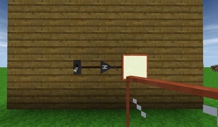
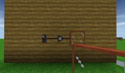
Delay Gate
This is the gates with "D" on it
- This gate uhh.... delays a signal.
- This gate also has one input.
- This gate delays the circuit for 0.2 seconds

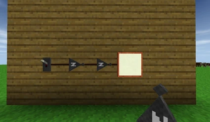
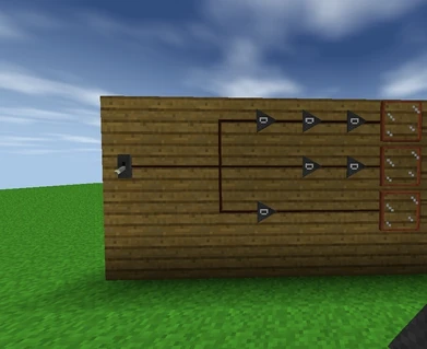
Delay Gates can be also chained -
- the "chained" means that the gates don't have any spaces between them
- when chained, the delays are - 1 sec (two gates), 5 secs (three gates), 9 secs (four gates) 13 secs (five gates) etc.
- when not chained the delays are - 0.2 secs (two gates with a wire between them), 0.4 secs (three gates not chained), 0.6 secs (four gates not chained) etc.
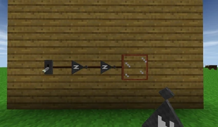
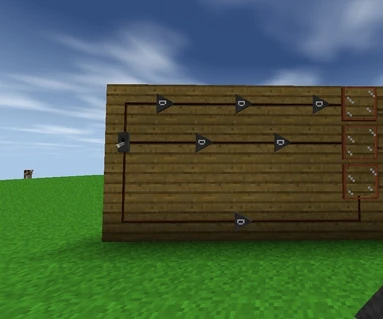
And an example of the how to get 0.4, 0.6, 0.8, etc.
We now know that delay gates delay ON signals but did you know that delay gates also delay the OFF signal?
They delay the off signal by the same amount of time they would with the on signal.
RECAP TIME!!!
- A Delay gate delays a signal (explaining the name "delay")
- The Delay Gate delays the on signal and the off signal
- They can also be chained to produce longer delays.
Adjustable Delay Gate
This is the gates with a black bordered "D" on it
- This gate delays a signal much like a traditional Delay Gates, however you chan adjust the delay by pressing the Edit Button
- You can set the delay of this gate from 0.01 to 2.56 seconds, by editing in hundredths of second
- If you need a wider delay, you can always chain two or more adjustable delay gates, however, the delay between the gates is not influenced if there's a space between them or not.
- Much like Delay Gate, this gate also has one input
Random Generator
It is the gate that has random looking scribbles on it
- The Random Generator does not require any input. It will continuously output a pseudo-random value and this value will change roughly twice per second.
- If a clock signal is connected, it will only output a value on the rising edge of this clock.
- It has only one output and one input.