This article presents timer circuits. Timers (as opposed to alarms) do not start automatically and either count elapsed time (stopwatch) or count down from a preset value (cooking timer). They may still trigger an alarm but only after a certain amount of time has elapsed.
All references in this article to 'seconds', 'minutes', etc mean SurvivalCraft 'seconds' etc. These are defined by the Real Time Clock outputs.
Day Counter[]
This circuit will keep track of the number of days since it was started up. It can be used to keep track of how long you are in a mine or to make sure you visit your animals regularly.
Operation[]
The day counter never stops. It constantly increases by one at midnight. You can tap the reset button to set the count to 0. It will start counting the number of days that pass.
How it works[]
The RTC (real time clock) output 3 indicates the hours with an analog signal. At midnight this signal changes from full on (F) to full off (0). This change is detected and inverted by the NOT gate and that triggers the (+) input on the 4-Bit Counter. The output of the counter feeds the 7-Segment Display.
The button is connected to the reset input on the 4-bit counter.
Pictures[]


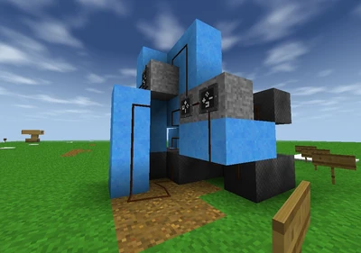
The front of the day counter.
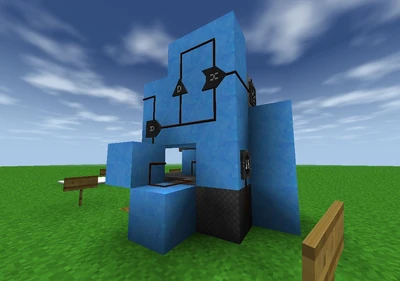
The back of the day counter.
Building it[]
As you can see, this timer is very simple to build. It only requires 1 RTC, 1 counter, 1 NOT gate, 1 display, 1 button, 1 wire, 3 wire-through blocks, and 1 other block.
The design above was laid out for minimum space and components. It can easily be adapted so that it's all hidden except the button and display.
Use[]
The picture below shows one application of the Day Timer. On the top is a clock with date display. The timer is below. With this setup, I can see what the date and time are now and hit the reset before I go to mine. Then when I get back, I'll know how long I was away as well as the current time and date. The werewolf early warning circuit (see Alarm circuits) can be added to the back of this since there are no "player serviceable parts" to it.

Stopwatch Timer[]
Here is a circuit for a minimum functioning stopwatch. You can start and stop it and reset it to zero. It reads out in SC hours/minutes/seconds.
Operation[]
The start/stop switch will stop and freeze the stopwatch when it is off (down). The stopwatch will begin again from that value when the switch is on (up).
Tap the reset button to set the timer back to all '0's. You can reset it when the timer is stopped or is running.
Building the stopwatch[]
Look at the 3 pictures provided. They show the front, back and side view of a working model. With enough electrics experience you can rebuild one from these pictures. However, it is not considered a simple circuit and a link to a map including this circuit will be provided shortly...
The circuit is laid out in the pictures such that you can build the display and switches into the face of a wall.
All unnecessary block are removed for clarity.


stopwatch front

Stopwatch Rear

Stopwatch side
How it works[]
There are 3 parts to this design. It starts with the 'oscillator' section which generates a pulse each second. The (analog) seconds output from an RTC is fed to an ADC to strip out the least significant bit - the fastest one. First it is gated through an AND gate so it can be turned off by the switch.
This bit changes state each second so is processed by a differentiator cuircuit as shown on the Clock / Pulse Circuits page. From the diff circuit, we get a pulse every second (or 1 Hz).
The one per second clock goes into a 3 stage counting circuit. The first counter is for the seconds. It is chained into the minutes counter which is chained into the hours counter. All 3 counters are reset to '0' when the reset switch is tapped.