This circuit is an expandable PIN lock that uses the latest in Survivalcraft technology. It is the most compact and advanced code lock in SurvivalCraft and has many features useful to the Adventure map maker.
Created by Stanimus using SurvivalCraft ver. 1.25
Operation
A PIN lock requires you to input a series of numbers to unlock it. This design displays the current number and has an UP button and a DOWN button next to each digit. Once you have your complete number displayed, you press the OPEN button (at the left). If the PIN is correct, the door will open and the digits all reset to zeros. If the PIN is NOT correct, all the digits will still reset to zeros but the door will NOT open.
Each digit in this design is a hexadecimal number so they can be from 0 through 9 and A through F (16 choices).
The pictures and download world use a 3 number PIN as the example.The design is modular and can be used with only 1 digit or expanded to many more (infinite?) digits.
Programming the code
The secret code can be reprogrammed in-game and MUST be set before the lock will work. An unprogrammed lock will NOT work even with all zeros. To program it, you edit each of the memory banks at the back of the digit modules.
To edit the memory walk up to it and face it. The sneak button in your HUD will turn to an EDIT button. Tap it to program the chip. The memory chart will show up and simply tap on the FIRST line of it. This will bring up your system's edit window. It should show you 16 zeros in a row.
The next part is the only slightly complicated part. You want to count from the left and change ONE of these '0's to an 'F'. If you change the first '0', that means you want the secret number to be a '0'. Look at the top of the memory chart. That shows you the number for each column. If you change the second column it will be a '1'. The next is '2' and so on. The last position will mean the secret digit is a 'F'. All other entries should be '0' except for the one you want to be the code number.
You only need to change the first line in any memory chip and you DO have to program EACH digit to SOMETHING or the lock will NEVER open. You can start it off at all zeros by putting an 'F' in the FIRST space on the FIRST line of EVERY memory chip.
Pictures
All the darker blocks are wire-through-blocks. Any of the (3) wire-through-blocks will work. All lighter blocks can be any block that a wire will stick to.
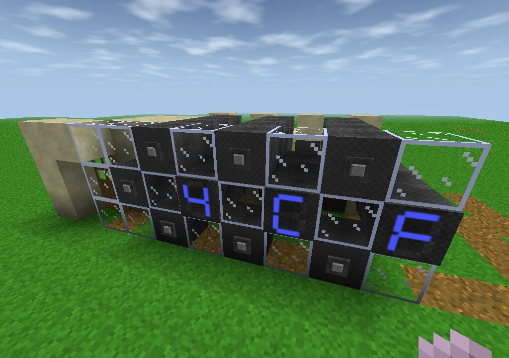
Font of PIN lock
The front of the lock. The button at the far left is the 'open' button. If the code is correct, it will open the door to its left.
The glass can be any decorative block desired. No wires need to be attached to them.
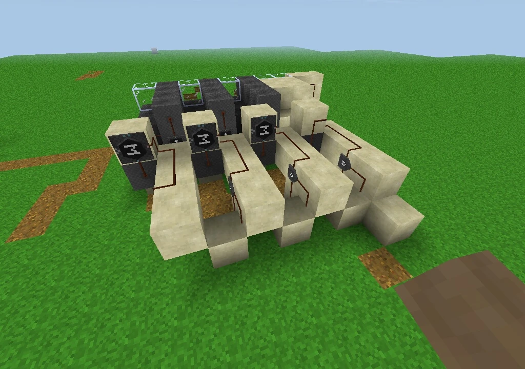
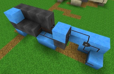
The back of the PIN lock. You can see the design is very modular and compact.
There are no wires on the top or sides so this circuit can be squeezed into an existing opening at least 3 blocks high and 10 deep. The extra block depth is to give you room to get in to program the memories.
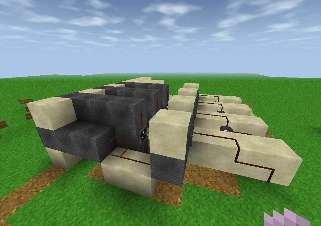
A side view (with the finished face blocks in place).

One digit module from overhead.

Each digit module has three sections to it; the counter, the memory and the combiner sections. They will link to another module placed next to them.
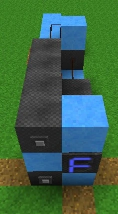
One digit module from the side. The buttons and display face to the left in this photo. You can (barely) see the counter, memory and the AND gate.
How It Works
Each digit is a separate module and they have three sections each.
The 1st section is the counter. This uses the two buttons, the digit display and a 4-bit counter chip. The design is very straightforward. You can see it built separately in the download world. This design has a master reset line to zero out all the counters.
The second section is the comparator. This section is at the back of the counter section. A memory bank is used to check the number from the counter. If it matches the one in memory, the output is activated. The number in memory can be changed any time by editing the memory chip. This section is simple, too. The design uses only one input of this chip and the one output.
The last section combines the outputs of all the digit modules. It is at the back of each digit module and uses just one AND gate.
In the design this output is combined with the 'open' button and that signal is used to open the door. The 'open' signal is also fed back to clear the counters. This keeps the 'secret code' from staying on the display after it's checked.
Extra features
- The design makes it easy to tap into either output signal (with or without the 'open' button included) for use in another circuit. Actually, any stage of the AND gates can be brought out of the circuit. They can be tapped from the back without making the lock any wider or taller. These outputs are however, pulsed because the counters are automatically reset. This pulse can easily be turned into a constant signal with more electrics if you wish.
- Some application may not want to have the counters reset and it is very simple to disable this function.
- The reset input line can be tapped into in order to disable the entire lock operation, including the counters and displays.
- For even more complex Adventures, the 'open' button signal can be brought out for options such as limiting the number of attempts the player is allowed.
- There is also an option to have another signal ANDed into the combiner section. This can prevent the lock from opening but the display will continue to operate as 'normal'.
- Any of these signals can be used to activate a sign that can inform the player of the situation whether it's a successful unlock, a 'try again', or a failed 'assignment' that needs to be complete before they can open the lock. These are just some examples.
- The memories can be programmed in more creative fashion as well. You can allow for 2 or more 'correct answers'. You could even let one digit (or all of them) be ANY number. To do this, program the memory with ALL 16 'F's in the first row.
Link
The ver. 2.0 compact lock can be downloaded HERE. This world has the 'finished' lock as well as one 'complete' digit module. It also shows the steps to construct each module. This should make it easier to see how to build it and easier to understand how it works. The secret code in the upload is already displayed on the lock.